|
|
本帖最後由 vegewell 於 2011-9-17 20:39 編輯
仔細看這裡有調整的軟體可下載 及How can I use more than one MaxSonar®-EZ1™
in the same system?
http://www.maxbotix.com/tutorials.htm#What_are_the_differances_between_the_Original_MaxSonar_EZ1_and_the_LV_MaxSonar_EZ1
=====================================
How can I chain multiple MaxSonar® sensors together?
There are multiple ways to use the sensors without interference. Three ways are described below.
Daisy Chaining using a Commanded Loop

Figure 6.5.
To chain the sensors, and have them operate in sequential daisy-chained fashion, you do so by linking the TX of unit 1 to RX of unit 2 and so on. The BW pin is tied high on all of the parts. Then just strobe the first sensor's RX pin and all of the sensors will read the range in sequence. The analog values can then be read. The example in Figure 6.5 would use one pin to command the chain, and three analog to digital inputs. Please click the link to the download the PDF file.Commanded Loop PDF File
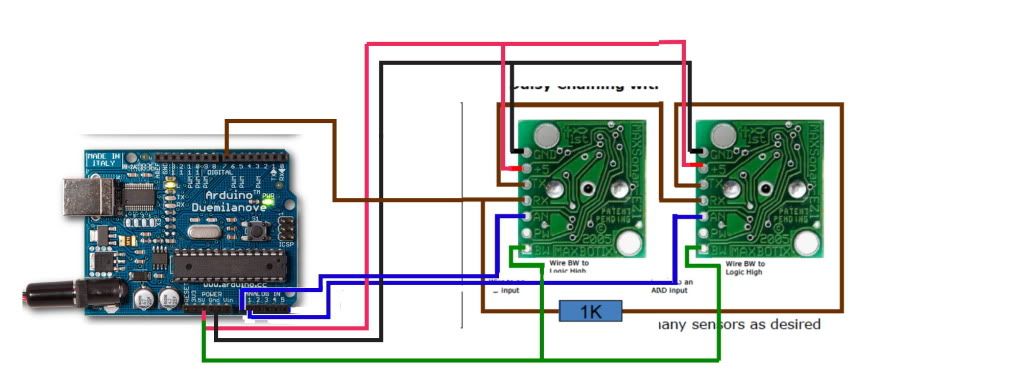
Daisy Chaining with Constantly Looping

Figure 6.6.
If you want them to keep running and constantly loop and always provide the latest range reading you will have to do two things.
First, add a resistor between the last sensor's TX back to the Rx of the first unit through a 1K resistor as shown in Figure 6.6.
Second, you will have to "kick start" them, (at least 250mS or more after power is applied to the sensors to give the sensors this time to boot-up). To do this, pull the RX pin high on the first sensor for at least 20uS. Then controller will have to return it's pin to a high impedance state so that the next time around the TX output from the last sensor will make it's way to the RX of the first sensor. Then all of the sensors in the chain will run in sequence. This "ring of sensors" will cycle around and around, constantly maintaining the validity of their analog values. You can then read the latest range reading (i.e. the analog value) at any time. This is the easiest way to use them.
After pulling the RX pin low, you can read the analog pin about 50mS (100mS if this is the first time reading the sensor as it calibrates upon the first commanded range cycle after power up, i.e. the sensor must complete a range cycle). In addition, the most recent range reading is always ready to be read on the analog voltage pin, so once you start the chain, and if you are using it in continuous mode, you can read the values at any time. Please click the link to download the PDF file. Constantly Looping PDF File
Simultaneous Operation

Figure 6.7.
You can also run them all at the same time (and for some uses this is preferred as the measurement speed is maximum, but it is only for selected applications). Just tie all of the RX pins together and command them with a pin from your microcontroller as shown in figure 6.7. Hold the pin high for more than 20uS. Do not continuously leave this pin high, as then all of the sensors will free run as described above. Command the sensors every 50mS or whenever a new range reading is desired. Please click the link to download the PDF file. Simultaneous Operation PDF File |
|


 發表於 2011-9-17 20:31:28