Robofun 機器人論壇

標題: EZ1超音波連接運用在ARDUINO上大問題! [打印本頁]

作者: yao412030    時間: 2011-9-16 19:24
標題: EZ1超音波連接運用在ARDUINO上大問題!
本帖最後由 yao412030 於 2011-9-16 19:32 編輯

小弟我的專題是運用EZ1兩顆超音波和ARDUINO做防碰撞自走車,我超音波裝置電源有和馬達分開用
現在我遇到一個很大的問題就是兩顆超音波同時工作時會出現干擾...輸出的類比值非常不穩定
數值會突然降低又拉上去
而我用單一顆超音波就不會有這個問題,我現在的接法是GND +5V AN直接拉ARDUINO
現在的問題就是兩顆同時工作會出現干擾造成我的車明明前面沒障礙物他就是會自己左右亂轉...
想請問這邊的神人有沒有辦法可以解決我的問題阿??
是否可以提供我兩顆EZ1串接同時使用時可以正常運作不互相干擾的電路圖或接法呢??
這個問題我已經卡了3個月了還是無解
真的是拜託大家幫幫我!!
謝謝!
作者: nichal    時間: 2011-9-17 07:16
把一顆石頭丟在水裡
水的漣漪遇到物體邊緣會產生反射漣漪
所以收到反射波就知道哪邊有障礙物

ok
那如果丟兩個石頭下去
還沒碰到障礙物就撞在一起的發射波
你會如何處理呢?
朝這個方向思考看看吧!!

如果是我
我可能會一次丟一個石頭就好
等上一個漣漪不見了
再丟下一個.....
不過丟石頭的位置可以不一樣
隨我高興~~~

試著用一個臉盆裝水
裡面直立幾根棒子 (模擬接收器的位置)
然後丟彈珠在水裡 (模擬發射器的波形)
觀察一下水波撞到棒子前的動作現象
應該可以找到很多想法.......
作者: vegewell    時間: 2011-9-17 20:31
本帖最後由 vegewell 於 2011-9-17 20:39 編輯

仔細看這裡有調整的軟體可下載 及How can I use more than one MaxSonar®-EZ1
in the same system?


http://www.maxbotix.com/tutorials.htm#What_are_the_differances_between_the_Original_MaxSonar_EZ1_and_the_LV_MaxSonar_EZ1
=====================================
How can I chain multiple MaxSonar® sensors together?
There are multiple ways to use the sensors without interference.  Three ways are described below.

Daisy Chaining using a Commanded Loop

Figure 6.5.


To chain the sensors, and have them operate in sequential daisy-chained fashion, you do so by linking the TX of unit 1 to RX of unit 2 and so on.  The BW pin is tied high on all of the parts.  Then just strobe the first sensor's RX pin and all of the sensors will read the range in sequence.  The analog values can then be read. The example in Figure 6.5 would use one pin to command the chain, and three analog to digital inputs. Please click the link to the download the  PDF file.Commanded Loop PDF File

Daisy Chaining with Constantly Looping


Figure 6.6.

If you want them to keep running and constantly loop and always provide the latest range reading you will have to do two things.


First, add a resistor between the last sensor's TX back to the Rx of the first unit through a 1K resistor as shown in Figure 6.6.

Second, you will have to "kick start" them, (at least 250mS or more after power is applied to the sensors to give the sensors this time to boot-up).  To do this, pull the RX pin high on the first sensor for at least 20uS.  Then controller will have to return it's pin to a high impedance state so that the next time around the TX output from the last sensor will make it's way to the RX of the first sensor.  Then all of the sensors in the chain will run in sequence.  This "ring of sensors" will cycle around and around, constantly maintaining the validity of their analog values.  You can then read the latest range reading (i.e. the analog value) at any time.  This is the easiest way to use them.


After pulling the RX pin low,  you can read the analog pin about 50mS (100mS if this is the first time reading the sensor as it calibrates upon the first commanded range cycle after power up, i.e. the sensor must complete a range cycle). In addition, the most recent range reading is always ready to be read on the analog voltage pin, so once you start the chain, and if you are using it in continuous mode,  you can read the values at any time. Please click the link to download the PDF file. Constantly Looping PDF File


Simultaneous Operation


Figure 6.7.


You can also run them all at the same time (and for some uses this is preferred as the measurement speed is maximum, but it is only for selected applications).   Just tie all of the RX pins together and command them with a pin from your microcontroller as shown in figure 6.7.  Hold the pin high for more than 20uS.  Do not continuously leave this pin high, as then all of the sensors will free run as described above.  Command the sensors every 50mS or whenever a new range reading is desired. Please click the link to download the PDF file. Simultaneous Operation PDF File
作者: nichal    時間: 2011-9-17 21:46
V大提供的連結很讚唷~~~
作者: yao412030    時間: 2011-9-17 22:07
回復 3# vegewell
V大您好....你PO這個東西小弟我之前就有找到了....
只是這三種方式我不太清楚用哪一個,我現在認為應該是用Simultaneous Operation
他那個電路圖有幾條線我真的搞不懂要怎麼接才好...
他的RX線是串聯EZ1  AN旁邊寫Wire AN to an AD input
和BW旁邊寫Wire BW to Logic High我就真的看不懂他到底要我接哪條線
可否請V大幫幫我....
我昨天去問專題老師還被罵說我沒做功課....我猜他也不會
只能請教神人們,幫幫小弟我吧!!!
作者: vegewell    時間: 2011-9-18 19:20
本帖最後由 vegewell 於 2011-9-18 21:23 編輯

這裡有人用四個, 放置 前 後 左 右不同方向,
http://www.ecs.umass.edu/ece/sdp/sdp11/soules/files/mdr_draft.pdf
你有沒有試過不同方向?
另外他們使用 LV-MaxSonar-EZ1 不是MaxSonar-EZ1,
我再多看看,知道再提供意見,
這裡只有 nichal大 比較像似可愛的神人,
nichal大會解釋得很清楚,難不倒他的.
作者: vegewell    時間: 2011-9-18 21:28
回復 5# yao412030
這裡有很詳細的說明(6 SENSORS):
http://arduino.cc/forum/index.php?topic=66765.0

請仔細看過後,有問題再逐一的提出,

下圖除了藍色線有問題外, 其餘的就照著做看看

    http://s3.amazonaws.com/twitpic/photos/full/349405101.png?AWSAccessKeyId=AKIAJF3XCCKACR3QDMOA&Expires=1316352760&Signature=%2FZbA6RpkjFafVqfZYKZQo%2BMtY2E%3D
作者: yao412030    時間: 2011-9-18 21:57
回復  yao412030
這裡有很詳細的說明(6 SENSORS):


請仔細看過後,有問題再逐一的提出,

下圖除了藍 ...
vegewell 發表於 2011-9-18 21:28

大大您第二個網址我不能開欸....
小弟我還會多多研究!!!
先謝謝您!
作者: yao412030    時間: 2011-9-18 21:59
本帖最後由 yao412030 於 2011-9-18 23:03 編輯
這裡有人用四個, 放置 前 後 左 右不同方向,

你有沒有試過不同方向?
另外他們使用 LV-MaxSonar-EZ1 不是 ...
vegewell 發表於 2011-9-18 19:20

大大您好~不同方向當然是不會有干擾問題
不過小弟我是要做自走車車子前方必須左右兩端需架設感測器,如果兩個感測器朝同方向發射就會干擾
我的是要同一方向放在左右邊不同位置,而我是買MaxSonar-EZ1請問還可以照接嗎??
http://twitpic.com/5s0yp9/full這是我找到的圖....他好像是Daisy Chaining with Constantly Looping
他的藍色線我有點搞不懂,他是三個sensor的AN拉出來接在一起在拉到ARDUINO的ANALOG即可??
還是三個連線一起之後再一個一個另外拉線出來到ARDUINO的ANALOG接腳呢??
有點看不懂還請大大指導!!!

作者: nichal    時間: 2011-9-19 10:31
我發現大家都把問題想得很複雜
然後找一堆更複雜的答案想盡辦法要理解它
卻忘了最根本應該知道的概念......

波形在傳遞有兩個特質
一個就是會衰減
另一個就是會碰撞反彈
所以我前面才提到要用臉盆裝水做一下實驗
應該不會花多少時間的

觀察後得到的第一個結論就是
波形同時發射一定會有問題
除非障礙物的條件是已知的
不然一定會有不同的發射波互相碰撞的問題發生
V大提供的連結資料有用示波器去觀察信號的強度
其實就是要說明能量衰減的問題
超音波不像水波用眼睛就看得到
必須透過示波器才能推論

舉個例來說
前面裝了左右兩側的發射器
也裝了左右兩側的接收器
先考慮左右輪替發射的情況
左邊發射時理論上左邊的接受器會立刻收到回應波
(通常程式都會用延遲來避開這一段信號不收)
那麼在沒有障礙物的情況下
右邊會緊接著左邊也收到回應波
問題這都不是反射信號
是在一發射就收到的........
所以決定在何時打開哪個接收器去收到信號
就是大大您目前迫切需要解決的問題
接收信號不一定要隨時都接收的
只要在該接收的時間才打開接收就好
超過就當成沒障礙物
概念就是這樣囉~~~~

然後
有一個已經發射的波形正在傳遞中
就一定要等到它衰減到夠小以後再發射另一個
不然一定會搞不清楚到底哪一個才是剛剛發射的
多小才叫夠小?
用示波器看就知道了......
作者: vegewell    時間: 2011-9-19 17:20
回復 10# nichal


    nichal大 已經把波形概念解釋得很清楚,
對此原理很清楚之後,寫起程式就會有秩序合邏輯.
作者: vegewell    時間: 2011-9-19 17:21
大大您第二個網址我不能開欸....
小弟我還會多多研究!!!
先謝謝您!
yao412030 發表於 2011-9-18 21:57


    這個網址我一下子就能開啟了,
你也應該開入去得到關鍵知識,
標題是   Wire logic high, multiple sensors.
http://arduino.cc/forum/index.php?topic=66765.0
作者: vegewell    時間: 2011-9-19 17:23
本帖最後由 vegewell 於 2011-9-19 17:24 編輯
我的是要同一方向放在左右邊不同位置,而我是買MaxSonar-EZ1請問還可以照接嗎??
http://twitpic.com/5s0yp9/full這是我找到的圖....他好像是Daisy Chaining with Constantly Looping
他的藍色線我有點搞不懂,他是三個sensor的AN拉出來接在一起在拉到ARDUINO的ANALOG即可??
還是三個連線一起之後再一個一個另外拉線出來到ARDUINO的ANALOG接腳呢??
有點看不懂還請大大指導!!!

yao412030 發表於 2011-9-18 21:59
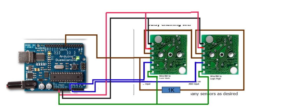
你找到的圖http://twitpic.com/5s0yp9/full,
就是我要說的那個圖,
Daisy Chaining with Constantly Looping
藍色的線,做者的說法是:
[blue lines were a little lazy, each AN from the sensor is going to a separate Analog pin on the board.
So Sensor 1 is going into ANalog pin 0 sensor 2 into Analog pin 1, etc.]
不過我認為都連結在一個pin也行,
========================
LV-MaxSonar-EZ1 比 MaxSonar-EZ1 容易連結使用幾個 sensors,(你要先努力嘗試使用手上的MaxSonar-EZ1)
如下圖serial timing那列有介紹:

作者: vegewell    時間: 2011-9-19 17:25
依照那國外做者,請先試試下圖的接法:


arduino的程式如下

int ultraSoundSignalPins[] = {0,1}; // 2 Ultrasound signal pins
int ultraSoundTriggerPin = 6;        // output pin to start Ultrasound signals


void setup() {
   Serial.begin(9600);
   for(int i=0; i < 2; i++) {
       pinMode(ultraSoundSignalPins, INPUT); // Switch signalpin to input
   }
   pinMode(ultraSoundTriggerPin, OUTPUT); // set this pin to output
  //give the sensors time to boot up
   delay(250);
   // send RX pin high to signal to chain to ping
   digitalWrite(ultraSoundTriggerPin, HIGH);
   delayMicroseconds(30);
   digitalWrite(ultraSoundTriggerPin, LOW);
   pinMode(ultraSoundTriggerPin, INPUT); // electrically disconnects the pin
   delay(50);
}
void loop()
{
   unsigned long ultrasoundValue;
   unsigned long echo;
   delay(50);
   for(int i=0; i < 2; i++)
   {
//Now the values from each sensor can be read:
       echo = analogRead(ultraSoundSignalPins); //Listen for echo
       ultrasoundValue = (echo / .58138);


       Serial.println();
       Serial.print("UltraSound Value");
       Serial.print( ultraSoundSignalPins);
       Serial.print(  "= ");
       Serial.print(ultrasoundValue);


   delay(500);
   
   }
  
}
==================
如有問題,
pin0 and pin1的線互換看看,
another 有沒有接 1 k 的電阻?
依照做者的說法,在測至一米前,都蠻(準確度)的 ,
作者: yao412030    時間: 2011-9-19 21:04
小弟我今天花了2小時把文章看了看一下,這幾天會開始實際操作~
謝謝大大們的詳細解說,如果有問題還要麻煩大大了~感恩
作者: yao412030    時間: 2011-9-19 22:33
回復 14# vegewell
大大您好
小弟我剛剛看了你PO的程式碼發現我編譯檢查時ARDUINO說有錯誤
sketch_sep19a.cpp: In function 'void setup()':
sketch_sep19a:8: error: invalid conversion from 'int*' to 'uint8_t'
sketch_sep19a:8: error: initializing argument 1 of 'void pinMode(uint8_t, uint8_t)'
sketch_sep19a.cpp: In function 'void loop()':
sketch_sep19a:28: error: invalid conversion from 'int*' to 'uint8_t'
sketch_sep19a:28: error: initializing argument 1 of 'int analogRead(uint8_t)'
sketch_sep19a:34: error: call of overloaded 'print(int [2])' is ambiguous
C:\Program Files\Arduino\arduino-0022\hardware\arduino\cores\arduino/Print.h:44: note: candidates are: void Print::print(const String&) <near match>
C:\Program Files\Arduino\arduino-0022\hardware\arduino\cores\arduino/Print.h:46: note:                 void Print::print(char, int) <near match>
C:\Program Files\Arduino\arduino-0022\hardware\arduino\cores\arduino/Print.h:47: note:                 void Print::print(unsigned char, int) <near match>
C:\Program Files\Arduino\arduino-0022\hardware\arduino\cores\arduino/Print.h:48: note:                 void Print::print(int, int) <near match>
C:\Program Files\Arduino\arduino-0022\hardware\arduino\cores\arduino/Print.h:49: note:                 void Print::print(unsigned int, int) <near match>
C:\Program Files\Arduino\arduino-0022\hardware\arduino\cores\arduino/Print.h:50: note:                 void Print::print(long int, int) <near match>
C:\Program Files\Arduino\arduino-0022\hardware\arduino\cores\arduino/Print.h:51: note:                 void Print::print(long unsigned int, int) <near match>

好像是這行開始出錯的pinMode(ultraSoundSignalPins, INPUT); // Switch signalpin to input
請問我該如何修改呢??
作者: vegewell    時間: 2011-9-20 09:43
解釋是:
[Analog pins are INPUT only, so there is no reason to set the pin mode for them.
As a result, the pinMode() function only applies to digital pins.
So, you just set digital pins 0 to 5 as input, including the ones managed by the Serial instance.]
所以你把下列幾行刪除試試(多餘的):
for(int i=0; i < 2; i++) {
       pinMode(ultraSoundSignalPins, INPUT); // Switch signalpin to input
   }
======================
作者: vegewell    時間: 2011-9-20 11:12
回復 16# yao412030


不過,沒有刪的原程式,
我現在自己用  Arduino Mega 去編譯 是 Done Compiling,
而且 Done uploading,
我是用最新版本 Arduino 0022,
你是怎麼用的?
原程式在此
http://arduino.cc/forum/index.php/topic,65727.0.html
  
作者: yao412030    時間: 2011-9-20 12:29
回復 18# vegewell
大大我發現你PO給我的程式碼和你給我樓上網址PO的程式碼有個地方不一樣才造成編譯錯誤!!
這次你PO給我的程式碼
pinMode(ultraSoundSignalPins, INPUT); // Switch signalpin to input
   }
這是樓上網址PO裡面的
pinMode(ultraSoundSignalPins, INPUT); // Switch signalpin to input
   }
我剛剛用樓上網址PO的程式碼進行編譯就OK了~
作者: yao412030    時間: 2011-9-20 18:19
依照那國外做者,請先試試下圖的接法:


arduino的程式如下

int ultraSoundSignalPins[] = {0, ...
vegewell 發表於 2011-9-19 17:25


小弟我現在在測試大大這張電路圖接法還有這個的程式碼http://arduino.cc/forum/index.php/topic,65727.0.html
小弟我發現當我使用5V的時候感測器都沒動作....
之後我降成3.3V之後感測器有動作而且兩顆不會互相干擾....
可是小弟我發現一個問題是當我手指整個蓋住感測器他的類比值是10
可是我把手拉到離感測器約8公分時類比值也差不多顯示10~12左右
請問大大有辦法解決這類比值數據上的間隔吧....這樣間隔實在是太小了
感謝囉!
作者: vegewell    時間: 2011-9-20 20:58
本帖最後由 vegewell 於 2011-9-20 21:18 編輯

回復 20# yao412030

那你也蠻會的, 知道要降至3.3V,
請問你是哪裡怎麼降至3.3V的?

你的意思是說,現在可以正確的顯示,至少誤差不會太大?
除了顯示值差距太小, 就沒有問題了嗎?

The LV-MaxSonar&reg;-EZ0™
detects objects from 0-inches to 254-inches
最長可偵測 是(6.45-meters),
那你想偵測的最遠為何?假設是100公分
假設0公分時類比值是10,  那100公分時假設類比值25,
所以你要在程式裡加入map()函數:
----------------------------------
ultrasoundValue = (echo / .58138);
ultrasoundValue = map(ultrasoundValue, 10, 25, 1000, 2500);
       Serial.println();
       Serial.print("UltraSound Value");
       Serial.print( ultraSoundSignalPins);
       Serial.print(  "= ");
       Serial.print(ultrasoundValue);
-------------------------------------
試看看 因為是long 不是int 所以不把握,
作者: yao412030    時間: 2011-10-4 18:53
回復 21# vegewell
大大您好阿....小弟我這幾天實在是在搞專題初審太忙了
現在才搞玩,第一階段算是順利過了
很謝謝您
至於我為什麼會知道要用3.3V是因為我測試結果發現5V整個做動非常不正常....
加上我知道這個感測器有5V和3.3V的工作電壓
所以我就測試就測出來囉....
至於類比值問題,小弟我會參考您提供給我的訊息!!!
現在為止目前做動是正常,可是還是有點問題...
小弟我就先謝謝大大指導囉!
作者: vegewell    時間: 2011-10-4 20:00
回復 22# yao412030

不客氣,
也謝謝你讓我有機會,更深入瞭解這個超音波元件.
我們一樣都是在網路上學習別人的知識
作者: yao412030    時間: 2011-10-15 22:10
本帖最後由 yao412030 於 2011-10-15 22:12 編輯

大大您好
小弟我又遇到問題了.....
就是小弟我有寫說如果左右兩科都偵測到障礙物時,要判斷哪邊距離障礙物比較遠,轉向離障礙物較遠的方向時
我的超音波類比值整個會怪怪的
假如說我前方有到牆壁,左邊比較接近牆壁,正常來說左邊類比值一定會小於右邊,可是我的卻不是,我的居然是左邊大於右邊...
反之也是一樣....
數值整個變非常奇怪,我也檢查我的程式碼好像也沒啥問題在....
我只用大大您提供的電路給我兩顆雖然不會互相干擾,左右其中一顆偵測到也不會發現說有類比值不穩的地方,可是兩顆同時偵測到就會出現問題
可否請大大幫助我呢?
謝謝!!
小弟我提供一下當兩邊都有遇到障礙物判斷距離轉向的寫法!!
}else if(right && left <= 30 && right<left){ //偵測到左右方障礙物且左方距離障礙物較遠減速轉向左方
      analogWrite(g_nMotor_2_Pin_B,255);
      analogWrite( g_nMotor_1_Pin_A, 0);
      analogWrite( g_nMotor_1_Pin_B , 120);
    l = 1;
  }else if (right >= 30 && right < left){ //偵測結束回復速度
      analogWrite( g_nMotor_1_Pin_A, 0);
      analogWrite( g_nMotor_1_Pin_B , 180);
  }else if(right && left <= 30 && right>left){ //偵測到左右方障礙物且右方距離障礙物較遠減速轉向右方
      analogWrite(g_nMotor_2_Pin_A,255);
      analogWrite( g_nMotor_1_Pin_A, 0);
      analogWrite( g_nMotor_1_Pin_B , 120);
  }else if (left >= 30 && right > left){ //偵測結束回復速度
      analogWrite( g_nMotor_1_Pin_A, 0);
      analogWrite( g_nMotor_1_Pin_B , 180);
    r = 1;
作者: vegewell    時間: 2011-10-16 13:37
本帖最後由 vegewell 於 2011-10-16 13:53 編輯

回復 24# yao412030


    你現在是移動轉向時,會有問題發生,
靜止時沒有問題,
是不是?
那麼是 MaxSonar-EZ1本身沒問題及與ARDUINO的連線沒問題,
對不對?
你只用一顆MaxSonar-EZ1面對兩個障礙物,移動轉向時會有問題發生嗎?
這個類比值是否符合兩個障礙物的距離?而不是有很多不同數值亂跳?

那麼可能就是設計上有問題,
先請問你的自走車有多寬?幾公分?
兩顆MaxSonar-EZ1相距幾公分?
兩顆MaxSonar-EZ1是平行的放置面對同一方向嗎?
作者: yao412030    時間: 2011-10-16 14:21
回復 25# vegewell
大大我是整台車架空起來測量.....
這是示意圖

正常來說距離牆壁10公分的類比值一定會比20公分的小....
可是我的剛好相反,導致我的車會轉向10公分的那方....
可是我程式碼沒有寫錯....不知道是不是那邊出了問題
作者: vegewell    時間: 2011-10-16 22:08
本帖最後由 vegewell 於 2011-10-16 22:10 編輯

回復 26# yao412030

你必須先確定是 MaxSonar-EZ1本身沒問題,
如果你沒驅使馬達轉動的時候,
兩顆MaxSonar-EZ1對著各種障礙物,包括你畫的圖這種角度對著牆壁,
兩顆MaxSonar-EZ1讀出的值是否正確?

如果正確,就表示 MaxSonar-EZ1本身沒問題,

至於你馬達的程式,因為我不曉得你是怎麼連線及控制馬達,
所以不曉得你的程式對不對,

如果你肯定正確的話,就表示最可能出現的問題是ARDUINO,
ARDUINO可能又控制馬達,造成電力不足,
所以有數值跳動的問題產生,
這種情形在ARDUINO控制servo時經常發生.
作者: vegewell    時間: 2011-10-16 22:57
回復 24# yao412030


    另外一種可能就是因為斜面折射的關係,
所以比較遠的那一顆接受到近的那顆的訊號,  而且比較多,
所以,以後每次在車子轉動時你就反過來寫,
大概如下:
}else if(right && left <= 30 && right>left){ //偵測到左右方障礙物且左方距離障礙物較遠減速轉向左方
      analogWrite(g_nMotor_2_Pin_B,255);
      analogWrite( g_nMotor_1_Pin_A, 0);
      analogWrite( g_nMotor_1_Pin_B , 120);
    l = 1;
  }else if (right >= 30 && right > left){ //偵測結束回復速度
      analogWrite( g_nMotor_1_Pin_A, 0);
      analogWrite( g_nMotor_1_Pin_B , 180);
  }else if(right && left <= 30 && right<left){ //偵測到左右方障礙物且右方距離障礙物較遠減速轉向右方
      analogWrite(g_nMotor_2_Pin_A,255);
      analogWrite( g_nMotor_1_Pin_A, 0);
      analogWrite( g_nMotor_1_Pin_B , 120);
  }else if (left >= 30 && right < left){ //偵測結束回復速度
      analogWrite( g_nMotor_1_Pin_A, 0);
      analogWrite( g_nMotor_1_Pin_B , 180);
    r = 1;
作者: yao412030    時間: 2011-10-17 22:30
回復 28# vegewell
大大您好,小弟我測試之後發現不管是架起來還是放在地上跑假如兩顆同時偵測到那個類比值就會很奇怪....
我自己也不知道要如何解釋....因為她每次詭異的狀態都不一定....
我在想我是不是用錯電路了...應該要使用Simultaneous Operation才對...
我現在還在思考這個問題,小弟我先謝謝您的協助了ˊ!!
我很感激!!
作者: vegewell    時間: 2011-10-18 17:50
回復 29# yao412030

不客氣,
也感謝你給我研究的動力,
試試 使用Simultaneous Operation的方式,也是應該的嘗試.
另外,如果你的自走車,
寬度不過十幾公分,
其實只用一顆MaxSonar-EZ1 也可以在碰到障礙物時,
知道要轉哪個方向,
如下舉例,給你參考:
http://megaswf.com/serve/1186867
作者: eat1256    時間: 2012-3-6 17:10
一樣坐在電腦前面上網聊天,
做一樣的事情,我卻有額外的收入。
網路創業的宅經濟網路世代,
唯一的風險就是你沒有參與!!

想在家工作,創造持續性收入!!
請點入註冊免費體驗90天>> http://litailhsu.blogspot.com/

(註冊成功後,請每天務必查收信箱重要信息!!)
作者: mjm2246    時間: 2012-4-24 20:32
Serial.begin(9600);
   for(int i=0; i < 2; i++) {
       pinMode(ultraSoundSignalPins, INPUT); // Switch signalpin to input
   }
   pinMode(ultraSoundTriggerPin, OUTPUT); // set this pin to output
  //give the sensors time to boot up
   delay(250);
   // send RX pin high to signal to chain to ping
   digitalWrite(ultraSoundTriggerPin, HIGH);
   delayMicroseconds(30);
   digitalWrite(ultraSoundTriggerPin, LOW);
   pinMode(ultraSoundTriggerPin, INPUT); // electrically disconnects the pin
   delay(50);


可以請問這段的意思是什麼
有點看不懂
謝謝


歡迎光臨 Robofun 機器人論壇 (https://www.robofun.net/forum/) Powered by Discuz! X3.2