Robofun 機器人論壇

標題: arduino 的學習之路..( Part. 1~11 ) [打印本頁]

作者: tommylin    時間: 2009-1-27 01:49
標題: arduino 的學習之路..( Part. 1~11 )
本帖最後由 tommylin 於 2012-9-10 14:57 編輯

arduino Mini + USB Mini
LCD 2x16
光敏電阻

尚未遮蔽 光敏電阻 的數值顯示在 LCD

遮蔽 光敏電阻的時候, LCD 數據降低.

[youtube]cp8Kv7xxNMY[/youtube]
作者: babyfish0226    時間: 2009-1-31 18:01
好一段時間沒玩Arduino了,看了影片,我也想翻出來重新玩了

另外youtube的影片只需要在編輯畫麵點插入youtube影片,然後帶入youtube連結中【v=】後面的參數就可以了,先幫您修正。
作者: tommylin    時間: 2010-2-17 02:06
先針對 Part. 1 做一些完整的補充..

[size=100%]~~ 安裝教學 Step By Step ~~

[size=85%]1. 先安裝電腦 Driver:
[size=85%]Download USBtoTTL Driver "CDM20600.exe",
[size=85%]下載連結 http://www.ftdichip.com/Drivers/VCP.htm
[size=85%]2. 將USB線插入電腦:
[size=85%]這時候打開工作管理員,
[size=85%]確認 COM PORT 的使用和驅動無誤( 使用的 PORT依情況會不同 ),
[size=85%]3. 執行 Arduino 0018:
[size=85%]設定 Tools->Board ( Arduino Mini )
設定 Tools->Serial Port ( COM 3)

[size=85%]4. 光感測器接線:
[size=85%]黑 - GND
[size=85%]紅 - 5V
[size=85%]白 - 信號 ( 接到 Arduino 的 digital pin 0 )
5. Parallax LCD接線:
GND
5V
RX  (接到 Arduino 的 TX)


[size=85%]~~ 使用材料 ~~
[size=85%]1. Arduino Mini.
[size=85%]2. USBtoTTL Board.
[size=85%]3. USB Cable.
[size=85%]4. 光感測器
[size=85%]5. LED
[size=85%]6. 麵包板.
[size=85%]7. Parallax LCD


// 程式碼 //
int ledPin = 13; // LED connected to digital pin 13
int PhotoSPin = 0; // Photosensitive connected to digital pin 0
int Analog_val =0; // Photosensitive Val

void setup()
{
    Serial.begin ( 9600 );

    pinMode(ledPin, OUTPUT); // LED
    pinMode(PhotoSPin, INPUT); // Photosensitive

}

void loop()
{
digitalWrite(ledPin, HIGH); // set the LED on
delay(Analog_val); // wait for a second
digitalWrite(ledPin, LOW); // set the LED off
delay(Analog_val); // wait for a second

Analog_val = analogRead(PhotoSPin); //讀取 光敏電阻 的數值

clearLCD (); // 清除 LCD 畫面

//===== 輸出數值到 LCD =====
Serial.print ( "Val= ");
Serial.print ( Analog_val, DEC );
Serial.print ( "\n");
}

// ===== clear the LCD =====
void clearLCD()
{
    Serial.print(12, BYTE);
}
作者: tommylin    時間: 2010-2-17 02:09
標題: arduino Mini 的學習之路..( Part -2 )
本帖最後由 tommylin 於 2010-2-18 20:10 編輯

看了網頁上的一些前輩教學,( http://accrochages.drone.ws/en/node/90 )
接續我的 Arduino Part -1 程式 ,
加入應用 Processing 實現了圖形化的數據顯示,
和學習 Serial Port 如何和 PC <-> Arduino 通訊,
一方面也學習使用 Java 底層的應用工具程式 Arduino / Processing
相關網站 www.Arduino.cc / www.processing.org
因為開始複雜化了.. 2 x 16 LCD 不敷使用了.
上面的曲線就是光敏電阻傳回來的數值.

實驗使用環境:
SONY CPU i5 (2.13GHz),  RAM 3GB,
Windows 7 (64Bit)
Arduino 0018
Processing 1.0.9

接下來 Project 越來越精彩了... 敬請期待~

http://tommylin99.blogspot.com )
作者: tommylin    時間: 2010-2-17 10:10
本帖最後由 tommylin 於 2010-2-18 20:08 編輯

課目: 伺服馬達的控制  ( PWM )

我這個實驗使用的是 Hitec HSR-8498HB 伺服馬達.
目前使用驅動模式選擇第一種已經成功.
這個馬達總共有3種模式,
1. Standard Pulse Mode (Pulse width 550 to 2450 Microseconds)
角度計算式 Servo Angle (degrees) = (Pulse Width (‧S) – 1500) / 10

2. Extended Pulse Mode. (Pulse width 50 to 200 Microseconds) (未完成)
3. Serial Mode. (Pulse width 416 Microseconds) (未完成)

範例程式:
#include


Servo myservo; // create servo object to control a servo

void setup()
{
myservo.attach(9); //連接 Servo 信號到 Digital Pin 9

myservo.writeMicroseconds( 1024 ); //Pulse width 550 to 2450 Microseconds = Standard Pulse Mode
}

void loop()
{}
作者: mzw2008    時間: 2010-2-17 12:21
呵呵
這是很好的教學哩, 繼續加油喔
不過為何你的arduino推的動馬達呢?
還是這顆馬達的電流需求不高!?

arduino mini 很迷你, 一組又便宜 ($450)
初學者玩這個就對了
作者: tommylin    時間: 2010-2-17 13:46
本帖最後由 tommylin 於 2010-2-17 13:55 編輯

[youtube]
<object width="425" height="344"><param name="movie" value="http://www.youtube.com/v/G94anJ9bXlo&hl=zh_TW&fs=1&"></param><param name="allowFullScreen" value="true"></param><param name="allowscriptaccess" value="always"></param><embed src="http://www.youtube.com/v/G94anJ9bXlo&hl=zh_TW&fs=1&" type="application/x-shockwave-flash" allowscriptaccess="always" allowfullscreen="true" width="425" height="344"></embed></object>
[/youtube]
成功設定 Servo 轉動角度,
讀取 servo 角度數值.

範例程式:
#include <Servo.h>

Servo myservo;  // create servo object to control a servo
void setup()
{
  Serial.begin( 19200 );
  myservo.attach(9);  //連接 Servo 信號到 Digital Pin 9
}
int angleVal=550;
void loop()
{
  myservo.writeMicroseconds( angleVal ); //Pulse width 550 to 2450 Microseconds = Standard Pulse Mode
  if ( angleVal + 100 <= 2450 )
   {
     angleVal += 100;
     delay ( 1000 );
   }
  else angleVal = 550;
  
  delay ( 300 );
  
  int readdata=0;
  readdata = myservo.read ();
  Serial.println ( readdata );
}
作者: tommylin    時間: 2010-2-17 13:54
呵呵
這是很好的教學哩, 繼續加油喔
不過為何你的arduino推的動馬達呢?
還是這顆馬達的電流需求不高!?
...
mzw2008 發表於 2010-2-17 12:21


Hi 鯨魚大大..
我直接用 Arduino 的 5V 接出來,
電表量馬達電壓大約 4.8 左右,
不知道電流多少 XD
只有接一顆應該OK吧~
作者: tommylin    時間: 2010-2-17 15:00
本帖最後由 tommylin 於 2010-2-17 15:01 編輯

更正~~~
剛剛確認下列的代碼是無效的... XD
myservo.read ();

等我研究清楚再來報告... Sorry ..
如果有哪位大大知道怎麼讀取 servo 數值的話,
請不吝賜教..謝謝嚕~
作者: mzw2008    時間: 2010-2-17 16:39
本帖最後由 mzw2008 於 2010-2-17 16:48 編輯

為何現在不能上傳圖片啊..
誰教我一下咧?

總之這顆要讀取資料得要...
A. 送出一個50us的high訊號
B. 送2~20us的low
C. SERVO會進入"暫停" low 狀態, 約125us
D. SERVO 會"傳回"一個high的訊號, 持續時間550~2450 (就是SERVO目前位置)
E. SERVO 回復LOW 250 us
F . 恢復原狀, SERVO又可繼續受到控制

因為這種讀取方式, 使得讀取位置的時候, SERVO會暫時停頓
SERVO的扭力和速度都會"暫時"減少, 所以不能用的太頻繁
作者: mzw2008    時間: 2010-2-17 16:51
這樣說好了, 他的原廠文件提到, 這東西要能精準控制
好像是使用Serial Mode會比較好, 能使用的指令會比較詳細和多功能
作者: tommylin    時間: 2010-2-17 21:40
感謝鯨魚大大的解說..
和 Datasheet 上面說的..
我有看沒有懂 = =
我目前功力不夠.. 所以先跳過了..
先進行下一個課目練習嚕~
作者: tommylin    時間: 2010-2-18 12:26
本帖最後由 tommylin 於 2010-3-10 16:29 編輯

網站好像不提供圖片上傳了..
先把圖上傳到別的網站..然後做連結... 測試一下...


作者: mzw2008    時間: 2010-2-18 12:38
原來如此...
不過這張照片不妥吧
等一下被愛護動物人士告虐待動物喔
作者: tommylin    時間: 2010-3-10 16:30
換了一張... 這張的背肌... 漂亮吧~
作者: tommylin    時間: 2010-7-11 11:19
本帖最後由 tommylin 於 2010-7-11 11:36 編輯

Part 4
控制 servo 轉動的速度,
而且要轉動的 Smooth
影片如下:
[youtube]rGG4y5_GM9A[/youtube]
原始碼如下:
#include <Servo.h>
Servo myservo;  // create servo object to control a servo
void setup()
{
  Serial.begin(9600);
  myservo.attach(9);
}
int pulse =2450;
int dir=1;
int offset=1;
void loop()
{
  myservo.writeMicroseconds( pulse );
  if ( pulse + offset >= 2450 ) dir = -1;
  else if ( pulse - offset <= 600 ) dir = 1;
  
  pulse += ( offset * dir);

  Serial.println ( pulse, DEC );
}
作者: tommylin    時間: 2010-7-11 15:43
本帖最後由 tommylin 於 2010-7-11 15:46 編輯

換轉動上臂的 servo , 最慢速..[youtube]9wN21YOj3AM[/youtube]
作者: tommylin    時間: 2010-7-11 15:47
本帖最後由 tommylin 於 2010-7-11 16:23 編輯

換轉動上臂的 servo , 中速..
[youtube]no3vtc-3zD8[/youtube]
作者: tommylin    時間: 2010-8-22 14:50
本帖最後由 tommylin 於 2010-8-27 11:48 編輯

arduino Mini 的學習之路..( Part -5 )
曠課了好久 @@ 把買了幾個月的零件翻出來試試,

課目: RGB Led 的控制.
電路圖:


這個實作..關鍵在電路板上印 "-" 的地方要接 DC + .. 不要問我為什麼(我也不知道)
程式中, pin 的 Value 255 是關閉 LED, 明暗的數值是 0~254 (靠 Gooooogle 老師教的 )

影片:
[youtube]evcyGZuxiNk[/youtube]
原始程式碼:
int R_ledPin = 9;
int G_ledPin = 10;
int B_ledPin = 11;
int ledPin = 13;
// val 255 = off
int R_val=254;
int G_val=254;
int B_val=254;

void setup()
{
    pinMode(ledPin, OUTPUT);
    pinMode( R_ledPin, OUTPUT);
    pinMode( G_ledPin, OUTPUT);
    pinMode( B_ledPin, OUTPUT);
    Serial.begin ( 9600 );

    analogWrite ( R_ledPin, R_val );
    analogWrite ( G_ledPin, G_val );
    analogWrite ( B_ledPin, B_val );
    delay ( 1000 );
}
int dir=0;
int color = 0;
int offset = 5;

void loop()
{
    digitalWrite(ledPin, HIGH);
    switch ( color )
   {
      case 0: analogWrite ( R_ledPin, R_val ); break;
      case 1: analogWrite ( G_ledPin, R_val ); break;
      case 2: analogWrite ( B_ledPin, R_val ); break;
   }
   if ( dir == 0 )
  {
      if ( R_val - offset > 0 )
     {
       R_val -= offset;
     }
     else
    {
      R_val = 0;
      dir = 1;
    }
  }
  if ( dir == 1 )
{
   if ( R_val + offset < 255 )
   {
     R_val += offset;
   }
   else
  {
    R_val = 254;
    dir = 0;
    if ( color + 1 < 3 ) color ++;
    else color = 0;
   }
  }
  clearLCD (); // 清除 LCD 畫面
  // 輸出數值到 LCD
  Serial.print ( "R= ");
  Serial.print ( R_val, DEC );
  Serial.print ( "\n");
}

// ===== clear the LCD =====
void clearLCD()
{
  Serial.print(12, BYTE);
}
作者: tommylin    時間: 2011-2-21 00:21
Part 6:
這個版好冷@@ 我來貼一些...
最近連續做了2個和馬達有關的練習..
提供各位參考嚕..

Stepper motor 步進馬達的控制:

步進馬達的控制:
把老舊的 彩色印表機拆了,
發現裡面有一顆步進馬達,
使用 Arduino 接上馬達的4條線,
我使用了 pin 9~12,
輕易控制馬達前進後退和速度..


Code:
#include

const int stepsPerRevolution = 100;

Stepper myStepper(stepsPerRevolution, 9,10,11,12);

void setup() {
myStepper.setSpeed(100);
Serial.begin(9600);
}

void loop() {
Serial.println("clockwise");
myStepper.step(stepsPerRevolution * 10);
delay(500);

Serial.println("counterclockwise");
myStepper.step(-stepsPerRevolution * 10 );
delay(500);
}


影片:
[youtube]F9liKrB990I[/youtube]


作者: tommylin    時間: 2011-2-21 00:27
本帖最後由 tommylin 於 2011-2-21 00:28 編輯

Part 7:
無刷馬達的控制..
在這個學習中使用了搖控直升機的 無刷馬達和電子變速器(ESC)
使用材料:
Align ESC BL15X
Align BL250 Brushless motor

動作說明:
提升馬達速度, 降低馬達速度, 暫停..

Code:
#include

Servo myservo;

void setSpeed(int speed)
{
int val = map(speed, 0, 100, 0, 180);
myservo.write(val);
}
void setup()
{
Serial.begin(115200);
myservo.attach(9);
}
void loop()
{
Serial.println("System Ready !!! Hit the 1 ");
do{ if ( Serial.read() == '1' ) break; } while(1);


int speed;

Serial.println("Throttle up");
for(speed = 37; speed <= 90; speed += 1) { setSpeed(speed); Serial.println(speed); delay(100); } setSpeed(30); delay(1000); Serial.println("Throttle down"); for(speed = 90; speed > 37; speed -= 1) {
setSpeed(speed);
Serial.println(speed);
delay(100);
}
Serial.println("waiting for 5 sec...");
setSpeed(30);
delay(5000);
}

//=============================
另外也可以用程式..取代使用遙控器油門設定電變(ESC)的方式
例如電變的 緩啟動, 煞車模式, 截止電壓...等..
依照不同廠商生產不同的電變而有所差異..

Code:
// 程式設定ESC 狀態
void AdjustESC ()
{
//plug ESC Battery first, when ESC start music ready, enter "1" in serial window
Serial.println("Enter Setup Mode");
do{ if ( Serial.read() == '1' ) break;
setSpeed(90);
} while(1);
delay ( 2000 );
setSpeed(30);

// waiting for ESC edit mode music and into brake edit mode,
// then enter "1" in serial window
Serial.println("Break Mode - soft Brake");
do{ if ( Serial.read() == '1' ) break; } while(1);
setSpeed(50);


Serial.println("Electronic Timing -Mid timing");
do{ if ( Serial.read() == '1' ) break; } while(1);
setSpeed(50);


Serial.println("Battery Protection - High cut off voltage protection");
do{ if ( Serial.read() == '1' ) break; } while(1);
setSpeed(30);


Serial.println("Aircraft Mode - normal airplane");
do{ if ( Serial.read() == '1' ) break; } while(1);
setSpeed(30);


Serial.println("Throttle response speed - Quick speed");
do{ if ( Serial.read() == '1' ) break; } while(1);
setSpeed(90);


Serial.println("BEC output voltage - 5.5V");
do{ if ( Serial.read() == '1' ) break; } while(1);
setSpeed(50);

}

影片:
[youtube]0yQ9MNKtyCA[/youtube]
作者: vegewell    時間: 2011-2-21 04:46
由電腦連接Arduino控制DC馬達(可正反轉)最簡單的方式為何?
作者: tommylin    時間: 2011-2-21 10:52
由電腦連接Arduino控制DC馬達(可正反轉)最簡單的方式為何?
vegewell 發表於 2011-2-21 04:46


   Vegewell 大大.. 您的問題很棒,也是我下一個想做的課目,
目前找到的資料都是針對 "碳刷馬達", "步進馬達"的方案,
我會繼續尋找 "無刷馬達"的正反轉方案...

如果有人已經玩過了, 也懇請幫忙解惑吧~
作者: coopermaa    時間: 2011-2-21 13:11
馬達好像可以用在非常多地方,好想有系統的學習馬達相關的知識
不知道這方面前輩都是看哪本書?
作者: nichal    時間: 2011-2-21 13:19
如果要控制無刷馬達
先確認有沒有感測器
有感測器的話要規畫三隻輸入腳

要透過Arduino控制的話
需要外接一片驅動板
(跟DC要外掛H Bridge一樣)
用六步方波控制需要六隻輸出腳
用弦波控制可以簡化到三隻輸出腳
不過要外接的硬體驅動板有支援dead time的調整
大致上是這樣

要知道無刷的控制方式
概念可以從這裡獲得
http://www.silabs.com/Support%20Documents/TechnicalDocs/An191.pdf
作者: vegewell    時間: 2011-2-21 15:14
回復 23# tommylin


    聽說:
[目前無刷馬達主要的應用大多在遙控航空模型上當做動力來源,但在益智娛樂機器人的使用上並不多,
目前市面上用於益智娛樂機器人的伺服機都還是使用有刷馬達做為主要的動力來源,]

為何要用無刷馬達?
難道無刷馬達可以跟步進馬達一樣精準控制嗎?
作者: vegewell    時間: 2011-2-21 15:18
本帖最後由 vegewell 於 2011-2-21 15:20 編輯

感謝nichal提供的資訊,

我的重點是由電腦直接控制 有減速電機的有刷馬達.
有一片arduino,
加上一顆 L298N 或是 SN754410 或是 TB6612FNG,
在加上電源.電阻. led 或二極體,
線接一接,應該就可以了,
拿到元件後就來試試,
如果成功,就po到這專題來.
作者: tommylin    時間: 2011-2-21 15:49
本帖最後由 tommylin 於 2011-2-21 15:52 編輯
回復  vegewell


    聽說:
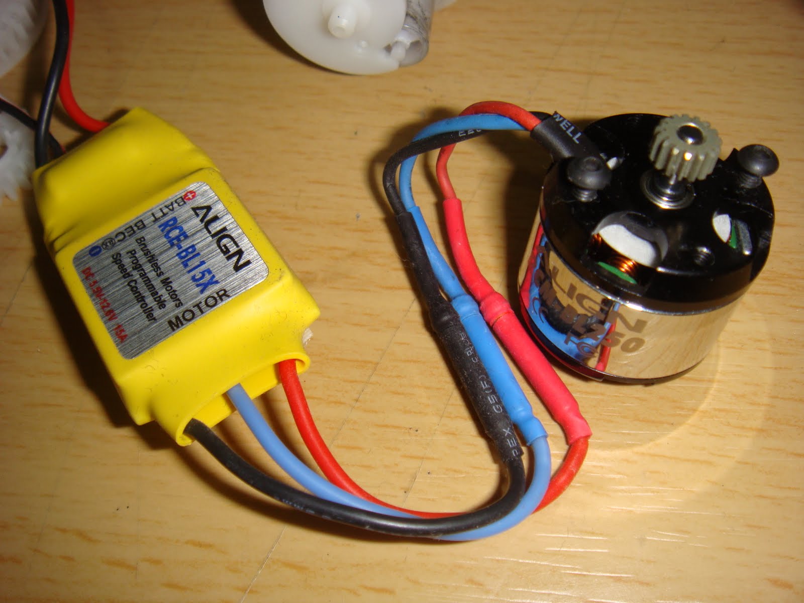
[目前無刷馬達主要的應用大多在遙控航空模型上當做動力來源,但在益智娛樂 ...
vegewell 發表於 2011-2-21 15:14


原因很單純的..
碳刷是直接接觸, 會磨耗...
作者: tommylin    時間: 2011-2-21 22:20
Part - 8:

讀取 Futaba 2.4G 接收機油門信號..配件:
Futaba FF9 2.4G 發射器
Futaba R617FS 2.4G 接收器

Arduino Pin 9 連接 接收器 pin 3 信號
11.1V 鋰電 和 Arduino 共地 (GND)

執行結果:顯示數值
油門最低點 110
油門最高點 191


Code:

unsigned long TransmitterThrottle=0;

void setup()
{
  pinMode (9, INPUT);

  Serial.begin(57600);
  Serial.println("System Ready~");
}

void CheckTransmitter()
{
  TransmitterThrottle = (pulseIn (9, HIGH, 200000))/10;
}

void loop()
{
CheckTransmitter();
Serial.print ("pulse: ");
Serial.println (TransmitterThrottle);

delay (200);
}

作者: vegewell    時間: 2011-2-22 22:01
無刷馬達, 比較貴.

大扭力無刷馬達:

----------------------------------------

作者: tommylin    時間: 2011-2-22 23:40
回復 30# vegewell

看起來這個有 遊星減速齒了,而且好像是傳說中可以調進角的馬達?
有這顆馬達的相關規格嗎?
多少齒比? 多少 Kv ? ... 多少錢 $_$
作者: vegewell    時間: 2011-2-23 10:40
回復 31# tommylin


    確實比較貴,
Mega Power TAURUS HV 4.5T
1/8車用感應式無刷馬達

訂         價 2000 元
ATM轉帳價 2000元
網路特惠價 2000元
每伏特轉速 4800rpm/V(KV)

http://rtc.ilinke.com/product/QyProductAction.do?func=detail&func=detail&pdt_mainid=P0066610
作者: vegewell    時間: 2011-2-23 11:03
操作有刷馬達的 L298N 或是 SN754410 或是 TB6612FNG,
只能承受2A,
不適合大扭力馬達.
作者: nichal    時間: 2011-2-24 18:14
無刷馬達其實不貴
(找同等輸出能力的碳刷馬達來比較的話)
貴的是馬達控制器......
因為碳刷馬達通直流就可以動(不需要控制器)
無刷沒有控制板就一定不能動
而高扭力(>1KW)的無刷控制板基本都要兩千以上(不含電源)
而500W左右的電變也在千把元左右
如果是考慮使用壽命的話
我想應該是值得投資的~~~~
作者: g921002    時間: 2011-2-24 21:56
感謝nichal提供的資訊,

我的重點是由電腦直接控制 有減速電機的有刷馬達.
有一片arduino,
加上一顆 L ...
vegewell 發表於 2011-2-21 15:18


用MOSFET搭H-Bridge控制吧!!一般L298N這類控制IC的驅動電流太低,不適合用在航模。
作者: g921002    時間: 2011-2-24 22:01
回復  tommylin
為何要用無刷馬達?
難道無刷馬達可以跟步進馬達一樣精準控制嗎?
vegewell 發表於 2011-2-21 15:14

1.無刷沒有電刷磨耗問題。
2.相同大小的馬達,無刷可以做到較大的扭力。
3.精準控制,可以。不過通常是搭配減速機。不管無刷有刷,直驅的控制線性度都不好,尤其在低速時。但是搭配減速機就能改善。
另外相同大小的步進馬達也無法提供跟無刷一樣大的扭力輸出。
作者: vegewell    時間: 2011-2-24 22:02
回復 34# nichal


    請問nichal:
我有一顆 6V大扭力直流有刷馬達,
馬達由 5v 100A電源供應器供電,
想接 5v雙刀雙擲繼電器,
並用Arduino控制, 控制正反轉.
大概如下圖:
http://slab.concordia.ca/wp-content/uploads/2008/09/img_0190-537x402.jpg
請問還要加上其餘元件嗎?
作者: vegewell    時間: 2011-2-24 22:03
回復 35# g921002

想用一顆繼電器試試,
不知行否?
作者: vegewell    時間: 2011-2-24 22:07
本帖最後由 vegewell 於 2011-2-24 22:08 編輯

此 超大扭力減速馬達
額定電壓:6V               
電壓範圍:3—9V
空載電流:700MA左右
額定電流:2A
轉速:6V電壓時,90轉/分
扭矩:20KG/CM
------------------------
看能否做為載重物的車輪.
作者: vegewell    時間: 2011-2-25 21:06
本帖最後由 vegewell 於 2011-2-25 21:21 編輯

我自己摸索的結果:
可以改成四個固態繼電器SSR-DD控制轉向,
要再接一個relay,讓馬達停止通電,
再裝一個 VPC光電耦合器, 保護arduino,
想接一個電子變速器ESC 或 n型mosfet irfz44n調整馬達速度,
其實也不必, 車輪載重物, 能滾動就不錯了.

另外最重要是煞車部份, 想裝個 電磁剎車片,
或再接一個relay,讓馬達兩端和GND短路造成煞車.

看來還有得喬....
作者: g921002    時間: 2011-2-25 23:52
回復 40# vegewell

您要不要另外開個主題。這樣比較好看到您老做的進度。
作者: nichal    時間: 2011-2-26 17:12
回復 37# vegewell


    就像G大說的
我是建議用MOSFET+H_Bridge控制
因為繼電器控制除了反應較慢(機械結構延遲)
還有火花的問題(接點容易因火花損耗造成接觸不良)
除非考慮隔離控制的需求
不然是不建議這樣用
作者: tommylin    時間: 2012-9-7 17:22
由於Arduino 整個系列全部買齊了,
接下來會包含 Arduino UNO-R3, Mini Pro, MEGA ..
所以改標題了~

Part 9: 有刷馬達的控制.
準備元件..
1. 有刷馬達.
2. 馬達控制器( pololu-Qik2s12v10 )


原始程式(來自 Pololu 官網)
  1. /*
  2. Required connections between Arduino and qik 2s12v10:

  3.       Arduino   qik 2s12v10
  4. ---------------------------
  5.           GND - GND
  6. Digital Pin 2 - TX
  7. Digital Pin 3 - RX
  8. Digital Pin 4 - RESET

  9. DO NOT connect the 5V output on the Arduino to the 5V output on the qik 2s12v10!
  10. */

  11. #include <SoftwareSerial.h>
  12. #include <PololuQik.h>

  13. PololuQik2s12v10 qik(2, 3, 4);

  14. void setup()
  15. {
  16.   Serial.begin(115200);
  17.   Serial.println("qik 2s12v10 dual serial motor controller");
  18.   
  19.   qik.init();
  20.   
  21.   Serial.print("Firmware version: ");
  22.   Serial.write(qik.getFirmwareVersion());
  23.   Serial.println();
  24. }

  25. void loop()
  26. {
  27.   for (int i = 0; i <= 127; i++)
  28.   {
  29.     qik.setM0Speed(i);
  30.     if (abs(i) % 64 == 32)
  31.     {
  32.       Serial.print("M0 current: ");
  33.       Serial.println(qik.getM0CurrentMilliamps());
  34.     }
  35.     delay(5);
  36.   }

  37.   for (int i = 127; i >= -127; i--)
  38.   {
  39.     qik.setM0Speed(i);
  40.     if (abs(i) % 64 == 32)
  41.     {
  42.       Serial.print("M0 current: ");
  43.       Serial.println(qik.getM0CurrentMilliamps());
  44.     }
  45.     delay(5);
  46.   }

  47.   for (int i = -127; i <= 0; i++)
  48.   {
  49.     qik.setM0Speed(i);
  50.     if (abs(i) % 64 == 32)
  51.     {
  52.       Serial.print("M0 current: ");
  53.       Serial.println(qik.getM0CurrentMilliamps());
  54.     }
  55.     delay(5);
  56.   }

  57.   for (int i = 0; i <= 127; i++)
  58.   {
  59.     qik.setM1Speed(i);
  60.     if (abs(i) % 64 == 32)
  61.     {
  62.       Serial.print("M1 current: ");
  63.       Serial.println(qik.getM1CurrentMilliamps());
  64.     }
  65.     delay(5);
  66.   }

  67.   for (int i = 127; i >= -127; i--)
  68.   {
  69.     qik.setM1Speed(i);
  70.     if (abs(i) % 64 == 32)
  71.     {
  72.       Serial.print("M1 current: ");
  73.       Serial.println(qik.getM1CurrentMilliamps());
  74.     }
  75.     delay(5);
  76.   }

  77.   for (int i = -127; i <= 0; i++)
  78.   {
  79.     qik.setM1Speed(i);
  80.     if (abs(i) % 64 == 32)
  81.     {
  82.       Serial.print("M1 current: ");
  83.       Serial.println(qik.getM1CurrentMilliamps());
  84.     }
  85.     delay(5);
  86.   }
  87. }
複製代碼

作者: tommylin    時間: 2012-9-7 17:39
一個小插曲.. 本來要先做 IMU 的學習..
但是... 買了一個超級爆笑的 IMU ... 來自對岸 = =
拍了照片..給大家笑一笑, 花了我不少錢學到教訓了@@


您看出哪裡有問題了嗎^^
作者: tommylin    時間: 2012-9-7 17:42
這張應該就看出來了吧 = =


作者: tommylin    時間: 2012-9-7 21:47
焊好接腳, 主角( qik 2s12v10 )登場..

作者: mzw2008    時間: 2012-9-7 22:05
一個小插曲.. 本來要先做 IMU 的學習..
但是... 買了一個超級爆笑的 IMU ... 來自對岸 = =
拍了照片..給大 ...
tommylin 發表於 2012-9-7 17:39


咦?
字顛倒
又沒焊接?
作者: tommylin    時間: 2012-9-7 23:13
回復 47# mzw2008

您真內行..字顛倒了, 呵呵~
作者: tommylin    時間: 2012-9-7 23:17
本帖最後由 tommylin 於 2012-9-10 17:11 編輯

先用 Arduino UNO - R3 頂著用..
義大利製造, 品質不是對岸能比的@@


要改裝的戰車...


分屍後~


這台是會打出bb彈的喔~

影片:
[youtube]kQzoKnWcxcM[/youtube]

接線圖:

作者: tommylin    時間: 2012-9-8 01:23
本帖最後由 tommylin 於 2012-9-9 12:51 編輯

PART 10: Wii motion plus + Nunchuck
我知道這已經過時很久了,
但是我蹺課太久了,現在捕回來@@


找到下列程式有一個重點,就是經過了 "Kalman Filter"的計算,
這樣才能夠實際應用, 不然一堆雜訊是沒辦法用的.
但是如果要更好的效果, 就要選用 9DOF IMU,
搭配Compass一起計算...這是後面的課題了..
  1. // Modified Kalman code using the Y-Axis from a Wii MotionPlus and the X and Z from a Nunchuck.
  2. // Nunchuck joystick provides corrections - X for Gyro, Y for Accelerometer
  3. // Also uses "new" style Init to provide unencrypted data from the Nunchuck to avoid the XOR on each byte.
  4. // Requires the WM+ and Nunchuck to be connected to Arduino pins D3/D4 using the schematic from Knuckles904
  5. // See http://randomhacksofboredom.blogspot.com/2009/07/motion-plus-and-nunchuck-together-on.html
  6. // Kalman Code Originally By Jordi Munoz... //Si deseas la version en Espanol, no dudes en escribirme...
  7. //
  8. // Altered by Adrian Carter <adrian@canberrariders.org.au> to work with WiiM+ and Nunchuck

  9. #include <math.h>
  10. #include <Wire.h>
  11. /////////////////////////////////////////
  12. #define NUMREADINGS 5 //Gyro noise filter
  13. // test for 3 axis
  14. int readingsX[NUMREADINGS];
  15. int readingsY[NUMREADINGS];
  16. int readingsZ[NUMREADINGS];                    // the readings
  17. int totalX = 0;
  18. int totalY = 0;
  19. int totalZ = 0;                                   // the running total
  20. int averageX = 0;                                  // the average
  21. int averageY = 0;
  22. int averageZ = 0;
  23. int lastaverageZ =0;
  24. // End of 3 axis stuff
  25. int readings[NUMREADINGS];                    // the readings from the analog input (gyro)
  26. int index = 0;                                    // the index of the current reading
  27. int total = 0;                                    // the running total
  28. int average = 0;                                  // the average
  29. int inputPin =0;                                  // Gyro Analog input
  30. //WM+ stuff
  31. byte data[6]; //six data bytes
  32. int yaw, pitch, roll; //three axes
  33. int yaw0, pitch0, roll0; //calibration zeroes
  34. ///////////////////////////////////////

  35. float        dt        = .06; //( 1024.0 * 256.0 ) / 16000000.0; (Kalman)
  36. int mydt = 20; //in ms.
  37. static float                P[2][2] = { //(Kalman)

  38.   {
  39.     1, 0   }
  40.   , //(Kalman)
  41.   {
  42.     0, 1   }
  43.   ,//(Kalman)
  44. }; //(Kalman)
  45. // extra 2 axis..
  46. static float                P1[2][2] = {  { 1, 0 } ,  { 0, 1 } ,};
  47. static float                P2[2][2] = {  { 1, 0 } ,  { 0, 1 } ,};
  48. static float                P3[2][2] = {  { 1, 0 } ,  { 0, 1 } ,}; //(Kalman)


  49. /*
  50. * Our two states, the angle and the gyro bias.  As a byproduct of computing
  51. * the angle, we also have an unbiased angular rate available.   These are
  52. * read-only to the user of the module.
  53. */
  54. float                        angle; //(Kalman)
  55. float                         angleX;
  56. float                         angleY;
  57. float                         angleZ;
  58. float                        q_bias; //(Kalman)
  59. float                         q_bias_X;
  60. float                         q_bias_Y;
  61. float                         q_bias_Z;
  62. float                         rate_X;
  63. float                         rate_Y;
  64. float                         rate_Z;
  65. float                         q_m_X; //(Kalman)
  66. float                         q_m_Y;
  67. float                         q_m_Z;
  68. float                         rotationZ;
  69. float                        rate; //(Kalman)
  70. float                         q_m; //(Kalman)

  71. // adjusts
  72. int gyro_adjust = 1;
  73. int accel_adjust = 128;

  74. int joy_x_axis = 0; //NunChuck Joysticks potentiometers
  75. int joy_y_axis = 0;
  76. int ax_m=0;        //NunChuck X acceleration
  77. // Re-added Y Axis
  78. int ay_m=0;        //NunChuck Y acceleration
  79. int az_m=0;        //NunChuck Z acceleration
  80. byte outbuf[6];                // array to store arduino output
  81. int cnt = 0;                //Counter
  82. unsigned long lastread=0;

  83. /*
  84. * R represents the measurement covariance noise.  In this case,
  85. * it is a 1x1 matrix that says that we expect 0.3 rad jitter
  86. * from the accelerometer.
  87. */
  88. float        R_angle        = .3; //.3 deafault, but is adjusted externally (Kalman)


  89. /*
  90. * Q is a 2x2 matrix that represents the process covariance noise.
  91. * In this case, it indicates how much we trust the acceleromter
  92. * relative to the gyros.
  93. */
  94. static const float        Q_angle        = 0.001; //(Kalman)
  95. static const float        Q_gyro        = 0.003; //(Kalman)

  96. void switchtonunchuck(){
  97. /*  PORTE ^= 32; // Toggle D3 LOW
  98.   PORTG |= 32; // Force D4 HIGH */ // Fast switching of pins... Arduino MEGA specific...
  99. digitalWrite(3, LOW);
  100. digitalWrite(4, LOW);
  101. digitalWrite(4, HIGH);

  102. }

  103. void switchtowmp(){
  104. /*  PORTG ^= 32; // Toggle D4 LOW
  105.   PORTE |= 32; // Force D3 HIGH */ // Fast switching of pins... Arduino MEGA Specific pin maps, so switched back to 'normal' code for example
  106. digitalWrite(3, LOW);
  107. digitalWrite(4, LOW);
  108. digitalWrite(3, HIGH);
  109. }

  110. void nunchuck_init () //(nunchuck)
  111. {
  112. // Uses New style init - no longer encrypted so no need to XOR bytes later... might save some cycles
  113. Wire.beginTransmission (0x52);        // transmit to device 0x52
  114.   Wire.write (0xF0);                // sends memory address
  115.   Wire.write (0x55);                // sends sent a zero.
  116.   Wire.endTransmission ();        // stop transmitting
  117.   delay(100);
  118.   Wire.beginTransmission (0x52);        // transmit to device 0x52
  119.   Wire.write (0xFB);                // sends memory address
  120.   Wire.write (0x00);                // sends sent a zero.
  121.   Wire.endTransmission ();        // stop transmitting
  122. }
複製代碼
//接後面
作者: tommylin    時間: 2012-9-9 12:53
  1. void setup()
  2. {
  3.   Serial.begin(115200);
  4. /*  DDRG |= 32; // Force D3 to Output // Arduino MEGA "fast" pin config. Reverted to 'normal' for example post.
  5.   DDRE |= 32; // Force D4 to Output
  6.   PORTG ^= 32; // Toggle D3 HIGH
  7.   PORTE ^= 32; // Toggle D4 HIGH */

  8.   pinMode(3, OUTPUT);
  9.   pinMode(4, OUTPUT);
  10.   digitalWrite(3, HIGH);
  11.   digitalWrite(4, HIGH);

  12.   Wire.begin ();                // join i2c bus with address 0x52 (nunchuck)
  13.   switchtowmp();
  14.   wmpOn();
  15.   calibrateZeroes();
  16.   switchtonunchuck();
  17.   nunchuck_init (); // send the initilization handshake

  18.   for (int i = 0; i < NUMREADINGS; i++)
  19.     readings[i] = 0;                            // initialize all the readings to 0 (gyro average filter)
  20. }

  21. void send_zero () //(nunchuck)
  22. {
  23.   Wire.beginTransmission (0x52);        // transmit to device 0x52 (nunchuck)
  24.   Wire.write (0x00);                // sends one byte (nunchuck)
  25.   Wire.endTransmission ();        // stop transmitting (nunchuck)
  26. }

  27. void wmpOn(){
  28. Wire.beginTransmission(0x53);//WM+ starts out deactivated at address 0x53
  29. Wire.write(0xfe); //send 0x04 to address 0xFE to activate WM+
  30. Wire.write(0x04);
  31. Wire.endTransmission(); //WM+ jumps to address 0x52 and is now active
  32. }

  33. void wmpOff(){
  34. Wire.beginTransmission(82);
  35. Wire.write(0xf0);//address then
  36. Wire.write(0x55);//command
  37. Wire.endTransmission();
  38. }

  39. void wmpSendZero(){
  40. Wire.beginTransmission(0x52);//now at address 0x52
  41. Wire.write(0x00); //send zero to signal we want info
  42. Wire.endTransmission();
  43. }

  44. void calibrateZeroes(){
  45. for (int i=0;i<10;i++){
  46. wmpSendZero();
  47. Wire.requestFrom(0x52,6);
  48. for (int i=0;i<6;i++){
  49. data[i]=Wire.read();
  50. }
  51. yaw0+=(((data[3] >> 2) << 8)+data[0])/10;//average 10 readings
  52. pitch0+=(((data[4] >> 2) << 8)+data[1])/10;// for each zero
  53. roll0+=(((data[5] >> 2) << 8)+data[2])/10;
  54. }
  55. }

  56. void receiveData(){
  57. wmpSendZero(); //send zero before each request (same as nunchuck)
  58. Wire.requestFrom(0x52,6); //request the six bytes from the WM+
  59. for (int i=0;i<6;i++){
  60. data[i]=Wire.read();
  61. }
  62. //see http://wiibrew.org/wiki/Wiimote/Extension_Controllers#Wii_Motion_Plus
  63. //for info on what each byte represents
  64. yaw=((data[3] >> 2) << 8)+data[0]-yaw0;
  65. pitch=((data[4] >> 2) << 8)+data[1]-pitch0;
  66. roll=((data[5] >> 2) << 8)+data[2]-roll0;
  67. }

  68. void receiveRaw(){
  69. wmpSendZero(); //send zero before each request (same as nunchuck)
  70. Wire.requestFrom(0x52,6);//request the six bytes from the WM+
  71. for (int i=0;i<6;i++){
  72. data[i]=Wire.read();
  73. }
  74. yaw=((data[3] >> 2) << 8)+data[0];
  75. pitch=((data[4] >> 2) << 8)+data[1];
  76. roll=((data[5] >> 2) << 8)+data[2];
  77. }
複製代碼
//接後面
作者: tommylin    時間: 2012-9-9 12:55
  1. void loop()
  2. {
  3.   if((millis()-lastread) >= mydt) { // sample every dt ms -> 1000/dt hz.
  4.     lastread = millis();
  5.     total += readings[index];
  6.     totalX += readingsX[index];
  7.     totalY += readingsY[index];
  8.     totalZ += readingsZ[index];                   // add the reading to the total
  9.     switchtowmp();
  10.     receiveData();
  11.     switchtonunchuck();
  12.     readings[index] = int(pitch/20); // read from the gyro sensor (/20 to get degree/second) pitch == roll
  13.     readingsX[index] = int(yaw/20); // read from the gyro sensor (/20 to get degree/second) pitch == roll
  14. //Continued
  15.     readingsX[index] = int(roll/20); // read from the gyro sensor (/20 to get degree/second) pitch == roll
  16.     readingsY[index] = int(pitch/20); // read from the gyro sensor (/20 to get degree/second) pitch == roll
  17.     readingsZ[index] = int(yaw/20); // read from the gyro sensor (/20 to get degree/second) pitch == roll
  18. //    receiveRaw(); // Provides unbiased output from WM+ (i.e, without calibrationZeros)


  19.     index = (index + 1);                          // advance to the next index

  20.     if (index >= NUMREADINGS)                   // if we're at the end of the array...
  21.         index = 0;                                    // ...wrap around to the beginning

  22.     average = (total / NUMREADINGS) - 511;
  23.     averageX = (totalX / NUMREADINGS) - 511;
  24.     averageY = (totalY / NUMREADINGS) - 511;
  25.     averageZ = (totalZ / NUMREADINGS) - 511;    // calculate the average of gyro input

  26.     q_m=((average*(joy_x_axis*0.00392156862))/(180/PI)); //GYRO convertion to Radian and external correction with nunchuk joystick
  27.     q_m_X=((averageX*(joy_x_axis*0.00392156862))/(180/PI)); //GYRO convertion to Radian and external correction with nunchuk joystick
  28.     q_m_Y=((averageY*(joy_x_axis*0.00392156862))/(180/PI)); //GYRO convertion to Radian and external correction with nunchuk joystick
  29.     q_m_Z=((averageZ*(joy_x_axis*0.00392156862))/(180/PI)); //GYRO convertion to Radian and external correction with nunchuk joystick

  30.     /* Unbias our gyro */
  31.     const float        q_X = q_m_X - q_bias_X; //(Kalman)
  32.     const float q_Y = q_m_Y - q_bias_Y;
  33.     const float q_Z = q_m_Z - q_bias_Z;
  34.     const float        q = q_m - q_bias; //(Kalman)

  35.     const float                Pdot[2 * 2] = {
  36.         Q_angle - P[0][1] - P[1][0],        /* 0,0 */ //(Kalman)
  37.         - P[1][1],                /* 0,1 */
  38.         - P[1][1],                /* 1,0 */
  39.         Q_gyro                                /* 1,1 */
  40.     };

  41.      const float        PdotX[2 * 2] = {
  42.         Q_angle - P1[0][1] - P1[1][0],        /* 0,0 */ //(Kalman)
  43.         - P1[1][1],                          /* 0,1 */
  44.         - P1[1][1],                          /* 1,0 */
  45.         Q_gyro                                /* 1,1 */
  46.     };

  47.     const float        PdotY[2 * 2] = {
  48.         Q_angle - P2[0][1] - P2[1][0],        /* 0,0 */ //(Kalman)
  49.         - P2[1][1],                          /* 0,1 */
  50.         - P2[1][1],                          /* 1,0 */
  51.         Q_gyro                                /* 1,1 */
  52.     };

  53.     const float        PdotZ[2 * 2] = {
  54.         Q_angle - P3[0][1] - P3[1][0],        /* 0,0 */ //(Kalman)
  55.         - P3[1][1],                          /* 0,1 */
  56.         - P3[1][1],                          /* 1,0 */
  57.         Q_gyro                                /* 1,1 */
  58.     };

  59.     /* Store our unbias gyro estimate */
  60.     rate = q; //(Kalman)
  61.     rate_X = q_X; //(Kalman)
  62.     rate_Y = q_Y;
  63.     rate_Z = q_Z;

  64.     /*
  65.          * Update our angle estimate
  66.               * angle += angle_dot * dt
  67.               *         += (gyro - gyro_bias) * dt
  68.               *         += q * dt
  69.               */
  70.     angle += q * dt; //(Kalman)
  71.     angleX += q_X * dt; //(Kalman)
  72.     angleY += q_Y * dt;
  73.     angleZ += q_Z * dt;

  74.     /* Update the covariance matrix */
  75.     P[0][0] += Pdot[0] * dt; //(Kalman)
  76.     P[0][1] += Pdot[1] * dt; //(Kalman)
  77.     P[1][0] += Pdot[2] * dt; //(Kalman)
  78.     P[1][1] += Pdot[3] * dt; //(Kalman)

  79.     P1[0][0] += PdotX[0] * dt; //(Kalman) X axis
  80.     P1[0][1] += PdotX[1] * dt; //(Kalman)
  81.     P1[1][0] += PdotX[2] * dt; //(Kalman)
  82.     P1[1][1] += PdotX[3] * dt; //(Kalman)

  83.     P2[0][0] += PdotY[0] * dt;//y axis
  84.     P2[0][1] += PdotY[1] * dt;
  85.     P2[1][0] += PdotY[2] * dt;
  86.     P2[1][1] += PdotY[3] * dt;

  87.     P3[0][0] += PdotZ[0] * dt;//y axis
  88.     P3[0][1] += PdotZ[1] * dt;
  89.     P3[1][0] += PdotZ[2] * dt;
  90.     P3[1][1] += PdotZ[3] * dt;

  91.     Wire.requestFrom (0x52, 6);        // request data from nunchuck

  92.     while (Wire.available ()) //(NunChuck)
  93.     {
  94.         outbuf[cnt] = Wire.read ();        // receive byte as an integer //(NunChuck)
  95.         cnt++;//(NunChuck)
  96.     }

  97.     send_zero (); // send the request for next bytes
  98.     // If we recieved the 6 bytes, then print them //(NunChuck)
  99.     if (cnt >= 5) //(NunChuck)
  100.     {
  101.         print (); //(NunChuck)
  102.     }
  103.     cnt = 0; //(NunChuck)

  104.     R_angle= (joy_y_axis+1)*0.0098039; //external adjust jitter of accelerometer with nunchuck joystick


  105.     const float                angle_m = atan2( ax_m, az_m ); //(Kalman)
  106.     const float                angle_err = angle_m - angle; //(Kalman)
  107.     const float                C_0 = 1; //(Kalman)
  108.     const float                PCt_0 = C_0 * P[0][0];  //(Kalman)
  109.     const float                PCt_1 = C_0 * P[1][0]; //(Kalman)
  110.     const float                E =R_angle+ C_0 * PCt_0; //(Kalman)
  111.     const float                K_0 = PCt_0 / E; //(Kalman)
  112.     const float                K_1 = PCt_1 / E; //(Kalman)
  113.     const float                t_0 = PCt_0; /* C_0 * P[0][0] + C_1 * P[1][0] (Kalman) */

  114.     const float                t_1 = C_0 * P[0][1]; /* + C_1 * P[1][1]  = 0 (Kalman) */


  115.     P[0][0] -= K_0 * t_0; //(Kalman)
  116.     P[0][1] -= K_0 * t_1; //(Kalman)
  117.     P[1][0] -= K_1 * t_0; //(Kalman)
  118.     P[1][1] -= K_1 * t_1; //(Kalman)
  119.     angle        += K_0 * angle_err; //(Kalman)
  120.     q_bias        += K_1 * angle_err; //(Kalman)

  121.           const float                angle_mX = atan2( ax_m, az_m ); //(Kalman) X axis
  122.     const float                angle_errX = angle_mX - angleX; //(Kalman) X axis
  123.     const float                C_0_1 = 1; //(Kalman) X axis
  124.     const float                PCt_0_1 = C_0_1 * P[0][0];  //(Kalman)
  125.     const float                PCt_1_1 = C_0_1 * P[1][0]; //(Kalman)
  126.     const float                E_1 =R_angle+ C_0_1 * PCt_0_1; //(Kalman)
  127.     const float                K_0_1 = PCt_0_1 / E_1; //(Kalman)
  128.     const float                K_1_1 = PCt_1_1 / E_1; //(Kalman)
  129.     const float                t_0_1 = PCt_0_1; /* C_0_1 * P[0][0] + C_1 * P[1][0] (Kalman) */
  130.     const float                t_1_1 = C_0_1 * P[0][1]; /* + C_1 * P[1][1]  = 0 (Kalman) */


  131.     P1[0][0] -= K_0_1 * t_0_1; //(Kalman)
  132.     P1[0][1] -= K_0_1 * t_1_1; //(Kalman)
  133.     P1[1][0] -= K_1_1 * t_0_1; //(Kalman)
  134.     P1[1][1] -= K_1_1 * t_1_1; //(Kalman)
  135.     angleX        += K_0_1 * angle_errX; //(Kalman)
  136.     q_bias_X        += K_1_1 * angle_errX; //(Kalman)


  137.     const float           angle_mY = atan2( ay_m, az_m );  // y axis
  138.     const float           angle_errY = angle_mY - angleY;  // y axis
  139.     const float           C_0_2 = 1;
  140.     const float           PCt_0_2 = C_0_2 * P2[0][0];
  141.     const float           PCt_1_2 = C_0_2 * P2[1][0];
  142.     const float           E_2 =R_angle+ C_0_2 * PCt_0_2;
  143.     const float           K_0_2 = PCt_0_2 / E_2;
  144.     const float           K_1_2 = PCt_1_2 / E_2;
  145.     const float           t_0_2 = PCt_0_2;
  146.     const float           t_1_2 = C_0_2 * P2[0][1];

  147.     P2[0][0] -= K_0_2 * t_0_2;
  148.     P2[0][1] -= K_0_2 * t_1_2;
  149.     P2[1][0] -= K_1_2 * t_0_2;
  150.     P2[1][1] -= K_1_2 * t_1_2;
  151.     angleY += K_0_2 * angle_errY;
  152.     q_bias_Y += K_1_2 * angle_errY;

  153.     const float           angle_mZ = averageZ/5;
  154.     const float           angle_errZ = angle_mZ - angleZ;
  155.     const float           C_0_3 = 1;
  156.     const float           PCt_0_3 = C_0_3 * P3[0][0];
  157.     const float           PCt_1_3 = C_0_3 * P3[1][0];
  158.     const float           E_3 =R_angle+ C_0_3 * PCt_0_3;
  159.     const float           K_0_3 = PCt_0_3 / E_3;
  160.     const float           K_1_3 = PCt_1_3 / E_3;
  161.     const float           t_0_3 = PCt_0_3;
  162.     const float           t_1_3 = C_0_3 * P3[0][1];

  163.     P3[0][0] -= K_0_3 * t_0_3;
  164.     P3[0][1] -= K_0_3 * t_1_3;
  165.     P3[1][0] -= K_1_3 * t_0_3;
  166.     P3[1][1] -= K_1_3 * t_1_3;
  167.     angleZ += K_0_3 * angle_errZ;
  168.     q_bias_Z += K_1_3 * angle_errZ;

  169.     rotationZ = angleZ;

  170.     Serial.print("average z ");Serial.print(averageZ);Serial.print("  lastaverage z ");Serial.println(lastaverageZ);
  171.     Serial.print("  angle_mZ = "); Serial.println(int(angle_mZ * 57.2957795130823));
  172.     Serial.print("Rate  ");Serial.print(int(rate*57.2957795130823)); Serial.print("  Angle X  "); Serial.print(int(angleX*57.2957795130823)); Serial.print("  Angle Y  "); Serial.println(int(angleY*57.2957795130823)); //Prints degrees Acceleromter+Gyros+KalmanFilters
  173.     Serial.print(joy_y_axis); //Prints the adjust for accelerometer jitter
  174.     Serial.print(" ");
  175.     Serial.print(int(angle*57.2957795130823)); //Prints degrees Acceleromter+Gyros+KalmanFilters
  176.     Serial.print(" ");
  177.     Serial.print(int(angle_m*57.295779513082)); //Prints the accelometer
  178.     Serial.print(" ");
  179.     Serial.println(joy_x_axis); //Prints the Gyro adjusment
  180.   }
  181. }
  182. void print ()//This is the function to get the bytes from nintendo wii nunchuck
  183. {
  184.   joy_x_axis = outbuf[0];
  185.   joy_y_axis = outbuf[1];
  186.   ax_m = (outbuf[2] * 2 * 2) -511; //Axis X Acceleromter
  187.   ay_m = (outbuf[3] * 2 * 2) -511; //Axis Y Acceleromter
  188.   az_m = (outbuf[4] * 2 * 2) -511; //Axis Z Acceleromter

  189.   // byte outbuf[5] contains bits for z and c buttons
  190.   // it also contains the least significant bits for the accelerometer data
  191.   // so we have to check each bit of byte outbuf[5]


  192.   if ((outbuf[5] >> 2) & 1)
  193.   {
  194.     ax_m += 2;
  195.   }
  196.   if ((outbuf[5] >> 3) & 1)
  197.   {
  198.     ax_m += 1;
  199.   }

  200.   if ((outbuf[5] >> 4) & 1)
  201.    {
  202.    ay_m += 2;
  203.    }
  204.    if ((outbuf[5] >> 5) & 1)
  205.    {
  206.    ay_m += 1;
  207.    }

  208.   if ((outbuf[5] >> 6) & 1)
  209.   {
  210.     az_m += 2;
  211.   }
  212.   if ((outbuf[5] >> 7) & 1)
  213.   {
  214.     az_m += 1;
  215.   }


  216. }
複製代碼
//程式結束

這個程式很好用,直接copy編譯就可以用,我實驗過了,效果真的很好,
訊號不會亂飄了~ 新手請安心服用嚕~
作者: nichal    時間: 2012-9-10 11:15
辛苦了~~~
練功果然是要花時間的!!
作者: babyfish0226    時間: 2012-9-10 11:57
超棒的分享,此篇已置頂並加入精華區
作者: tommylin    時間: 2012-9-10 14:45
本帖最後由 tommylin 於 2012-9-10 16:31 編輯

實在不好意思, 野人獻曝了..
To: nichal .. 因為興趣和現實要兼顧阿...呵呵~ 還要請你多多指導喔.
To:娃娃魚版大.. 太謝謝你了,這樣就比較好找帖子了..不會沉下去了 @@

我覺得國外的討論版真正會分享原始程式/硬體的很多,(其實國外網站口水也是很多)
我也只是順手貼到這裡,也會註明原始出處(通常都在程式碼裡面)..
希望年輕人如果因為英文苦手...
這裡可以提供一些線索和方向,
進入正題 ....

PART- 11: 平衡
這個課題估計我要學好幾年了,
試用了一堆板子,讀了一堆文章,最後選定了 MultiWii 來當做教材.
( http://www.multiwii.com )
(超級風行的 UAV 學習課題,學問超級多,範圍超級廣,每個功能都是一門專業的學問)
控制板: MultiWii All In One 主板
( Arduino Mega 2560, MPU6050, HMC5883L,MS5611 )
飛行機構: 泰世-四軸飛行器 330X


為什麼要選擇 MPU6050,希望專家能提供精闢的專業解說...
這個價位是我能負擔且效果最好的了..
但是只要你看過應用 MPU6050的實例,
應該都會認同 C/P值很好吧..@@
也有找到一顆超過 1000美金的,(但是我買不起 = = )
因為我要做的機器人需要不只一顆, 所以..

說明書中提到可以控制的多軸飛行器種類如下:


BiCopter就是俗稱的 阿凡達啦~
作者: mzw2008    時間: 2012-9-10 22:17
讚喔!!我之前都用ardupilot
現在也改進到APM 2.5版了
能把程式改穩定真是件不容易的事情哩
但現在有個想法
這改用ARM系統來做感覺會更好耶
時脈將進100M ,快了五倍,記憶體也多了很多,IO多很多可以接更多東西,算的更快反應也快
但似乎價格沒有高很多
作者: tommylin    時間: 2012-9-10 22:44
本帖最後由 tommylin 於 2012-9-10 22:51 編輯

感謝,鯨魚大大提出建議, 等我先把這個搞定再追品質嚕 ^^

Sensor 讀到信號了,除了 GPS沒時間玩, 現在都到齊了..
本來只要 ACC, GYRO, MAG, AHRS,
現在多了 高度計..
有圖有真相喔 .. (要學的東西好多阿~~ 爽~)

作者: mzw2008    時間: 2012-9-11 14:58
哇!!!
請問這是直接輸出到遙控上面嗎?
作者: tommylin    時間: 2012-9-11 15:48
回復 58# mzw2008

沒啦...只是顯示在 PC端的 GUI.
作者: tommylin    時間: 2012-9-11 23:50
因為重要的零件等待從德國飛來,
先來學習一下機構相關的設計..
算是番外篇吧.. 看圖:

片身+凹巢然後用鋁柱+螺絲強化結構,組成立體的機身,
看來我機器人的機構也可以自己用CNC這樣製作..

加上馬達後,覺得也是很堅固耶~

作者: tommylin    時間: 2012-9-12 00:03
另外一個好東西,從法國寄來的,
Arduino Mini Pro ready to use.

後面會介紹應用的內容..
作者: nichal    時間: 2012-9-12 18:05
是我該向 tommylin 大大請益才是
一整個pro級的呀!!!
作者: mzw2008    時間: 2012-9-12 18:13
咦?!
這看起來就是普通的Arduino Mini Pro
焊接成八角型以便出線而已
或是他的背後有特殊功能呢?
作者: tommylin    時間: 2012-9-13 00:22
回復 62# nichal

我繼續趕進度..很快要向您請教有關 PID.
作者: tommylin    時間: 2012-9-13 00:23
回復 63# mzw2008

沒有特別的, 只是因為我開始趕進度,
沒時間焊那些接腳了~~
作者: tommylin    時間: 2012-9-13 00:32
也要開始 機構設計了...
第一步: 先把要用的 Servo 模型建出來,
本來按照著 說明書的尺寸做,
結果servo拿出來發現~~~~ 怎麼標示的不一樣@@


我建好的模型~


用這個 servo的模型為基礎, 開始先在 SketchUp 設計心中的機器人,
這樣尺寸才會符合~
作者: tommylin    時間: 2012-9-13 14:02
剛剛收到了,
從德國漢堡寄來的 FreeIMU 最新版 0.4.3
我要將這用在我機器人的 "平衡中樞".
看圖嚕~

終於全部的零件都到齊...要開始整合了,
要做的事情還真多~ 全部靠自己一個人做,
不知何年何月才能實現夢想阿~_~

有同好要一起圓夢的嗎?
作者: tommylin    時間: 2012-9-13 18:49
做好的 servo 模型,
放到 Unity3D 裡面,
把 servo 指定軸向連接...
先暫時做個模擬影片.
[youtube]JviwOU0tL38[/youtube]
作者: tommylin    時間: 2012-9-14 00:05
本帖最後由 tommylin 於 2012-9-17 11:47 編輯

更新一下.. FreeIMU 0.4.3的效果,
現在存在一個 bug.. Yaw會飄移...

影片:

[youtube]J_0Yq5Sn7mc[/youtube]

今天是 2012-09-17 先不要買這個版..
等解決後再買..
已經有校正Yaw的解決方案了,
只是需要時間移植程式到 Arduino LIB
作者: tommylin    時間: 2012-9-17 12:11
要採用 鋰電池當做機器人的電源,
就當買個保險.. 一個好物 - "鋰電警報器",
低電壓的時候會大叫~ ~

正面照:

背面照:

數字顯示電壓值,
會輪流顯示每個 Cell,
然後再顯示總體電壓.
作者: tommylin    時間: 2012-9-17 12:17
組裝, 接線... (好亂的桌面...該整理了)
四顆同時叫還真是有趣,
實機看起來好小,也就兩個手掌大..
接下來測試馬達轉向/位置, RC Channel, LED...等的接線正確性...

作者: tommylin    時間: 2012-9-17 12:21
附帶一題...新手請勿急著安裝 "槳"... 會變血滴子,
貼張貼紙在馬達軸上就可以看出轉向了..
千萬注意安全,這不是玩具,是殺人飛行器...
就像機器人的 servo 一樣, 夾到手指也是很痛的 @@
作者: tommylin    時間: 2012-9-17 12:27
本帖最後由 tommylin 於 2012-9-18 00:52 編輯

另外一個好物到了... SSC-32

這是第二版的.

要用 Arduino Uno 連接 SSC-32 同時控制 32顆 servo,
先貼上接線圖說明..
直接接電腦就可以控制,要插上2個jump

要接 Arduino,拔掉上面 2個jump,
只要兩條線.. SSC-32的 RX 接到 Arduino 的 TX, 然後共地.

作者: tommylin    時間: 2012-9-18 00:40
本帖最後由 tommylin 於 2012-9-18 00:43 編輯

露天牌 9dof 終於測試出正確的接腳了... = =
看圖吧~

如果有人買到的話, 參考我的接腳吧 ...
只要四條線就可以了,
Arduino           露天牌 9dof
+5V                +5V
GND                GND
A4                   SDA
A5                   SCL
就是你看的懂英文字的那四個 @@
作者: tommylin    時間: 2012-9-18 00:55
今天忍不住先全部 Servo 同時啟動...
重溫當年第一次狼狽爬樓梯的感動了,
馬上要機體大改了... 留張遺照 = =

作者: tommylin    時間: 2012-9-18 12:29
目前測試過比較好的是 AHRS..
使用的是:
9 DOF IMU
陀螺儀ITG3205/ITG3200
加速度計ADXL345
數位羅盤HMC5883L

看起來不會飄移了, 但是還要再嚴格的測試.
影片:
[youtube]wJGqAQIdKvs[/youtube]
作者: tommylin    時間: 2012-9-18 14:03
本帖最後由 tommylin 於 2012-9-18 14:53 編輯

實際上我的磁場偏移嚴重,需要校準..
位處於地球的某的地方都會需要加入偏移值..


到 美國國家地球物理中心 http://www.ngdc.noaa.gov
查詢台北的位置結果..

這是我用 iPhone 顯示的..

作者: trance2000    時間: 2012-9-19 15:13
版主用的東西都還不錯,價格應該都不便宜吧
作者: playrobot    時間: 2013-1-14 20:03
你也許可以看看我們的網站, 有非常多的範例

飆機器人快速上手中心
https://sites.google.com/site/playrobotquickstart/


歡迎光臨 Robofun 機器人論壇 (https://www.robofun.net/forum/) Powered by Discuz! X3.2